Hacked Hard-disc Centrifuge
Fast spinning hard drives in a solid aluminium housing are perfect for making small DIY centrifuges...
DIY

Bengt's 7200 rpm IBM Deskstar with lasercut holder for 2 x 1.5ml Eppendorf tubes and 2 x 200 ul Eppendorf PCR tubes.
Needs tape to hold tubes down and preferably a box around it to avoid getting hit by flying tubes...

First GaudiLabs version of a hard drive centrifuge based on 3D printed tube holder. 3D printing is not precise enough for high speed applications...

Second try using laser cut acrylic parts. Now upgraded with a nice LCD display.
Ordered a appropriate driver: Electronic motor control for hopyy cars...

And another one, this time more safe with a metallic lid...
I will love to explain here something more about this motors and the electric parts behind. Most of the HDD motors are BLDC (brushless) motors. They can be driven by brushless ESC. Cheapest would be to buy hobby RC ESC and drive it by PWM
I find this nice tutorial from http://www.instructables.com/id/ESC-Programming-on-Arduino-Hobbyking-ESC/ I'm going to show you, how to program and use the Hobbyking ESC. I just found a few information and tutorials, which really didn't help me very much, so i decided to program an own sketch, which is very simple to understand.
Important to know:
- ESC means Electronic Speed control
- The ESC has a 5v(not used), GND and Signal Pin like a Servo
- You control it like a Servo with write() http://arduino.cc/de/Reference/ServoWrite
- or writeMicroseconds http://arduino.cc/de/Reference/ServoWriteMicroseconds
In my Example i use writeMicroseconds, because it is easier to understand.
Step 1: Getting ESC information
You really should remark the Amperevalue of your ESC. This tutorial is only tested on 20 AMP ESC : http://www.hobbyking.com/hobbyking/stor /__15202__hobby_king_20a_esc_3a_ubec.html I can't really promise, that this is working with an other ESC but i think so, because in the english manual are 20 and 30 Amp ESC's described. In the German version is a generalisation from 10 to 120 Amp, thats why I think this could work for every ESC.
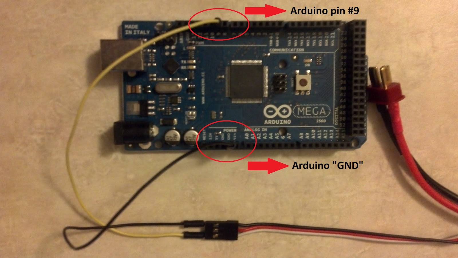
Step 2: Connection to Arduino I tried it with an arduino uno R3. First you have to connect the ESC to you lipo or NiMH. When you have done that you connect the ESC like so:
- Black to GND
- White/Yellow to PIN 9
Because you connected the ESC to your battery, the ESC is put under voltage. Thats why it It is important, that you DON'T connect the red wire to your 5v Port, because it could destroy your computer's USB Port. On this picture you can see the correct connection between ESC and Arduino (Mega). Picture source: http://1.bp.blogspot.com/-eqDaRgO5FjU/T9U3avwT2-I/AAAAAAAAALE/-8pj4qD12Q0/s1600/Figure2_2_edit.jpg
media:HDDCentri_Inlay_Laser.pdf
//////// other code to crontrol this motors /////
Sorry about that. No, there is only one for each, but the parts of the array are the pins:
motor_left[0] = pin 5, and [1] = pin 6.
Uh, the whole sketch is fairly large all up, but separated into three files, one with the drive functuions (forwards, back, left, right), the main one, and one with other stuff. By Ro-Bot-X @ Wed, 2011-02-02 14:48 Pins 5 and 6 are both PWM
Login or register to post comments
Pins 5 and 6 are both PWM pins tied to Timer0. You need to connect one of them to motor_left and the other to motor_right. Then the second pin of the motors can be a regular digital pin (for example 4 and 7). Lets group the pins like this:
- define motor_left_0 4 // direction pin, set it LOW for forward, HIGH for reverse
- define motor_left_1 5 // PWM pin, 0-255 values
- define motor_right_1 6 // PWM pin
- define motor_right_0 7 // direction pin, set it LOW for forward, HIGH for reverse
The enable pins have to be connected to Vcc (5V).
When driving forward, you set the direction pin LOW. A PWM value of 0 will have the motor stopped, then higher values make the motor spin faster and faster, 255 being the max speed.
When driving in reverse, you set the direction pin HIGH. A PWM value of 255 will have the motor stopped and lower vales will make the motor spin faster and faster, 0 being the max speed. To make this easy to use, just subtract the desired PWM value from 255 to get the inverted one, like this:
byte setPWM = 200;
//forward digitalWrite(motor_right_0, LOW); analogWrite(motor_right_1, setPWM);
//reverse digitalWrite(motor_right_0, HIGH); analogWrite(motor_right_1, 255-setPWM);
Does this look clear enough?
an example of a driver for a brushless DC motor without Microcontroler
   Control method: open loop, no feedback
   CPU: none
   Power source: 4x AA NiMH
   Sensors / input devices: none
   Target environment: ex hard drives
other posibilitie:
http://www.bajdi.com/obstacle-avoiding-robot-made-from-cheap-parts/l293d-schematic/
[[1]]